Building an Altimeter with Arduino

Learning new things regularly is important. I make it a habit to find new things to learn even when they do not have a direct focus on information security. Projects like this give me a chance to draw upon a more broad set of experiences in the work I do, and are extremely satisfying when done, enjoy!
What You'll Be Doing
- Solder components to the included circuit board.
- Solder each joint where two pieces of copper tape meet and where the tape is next to the pin.
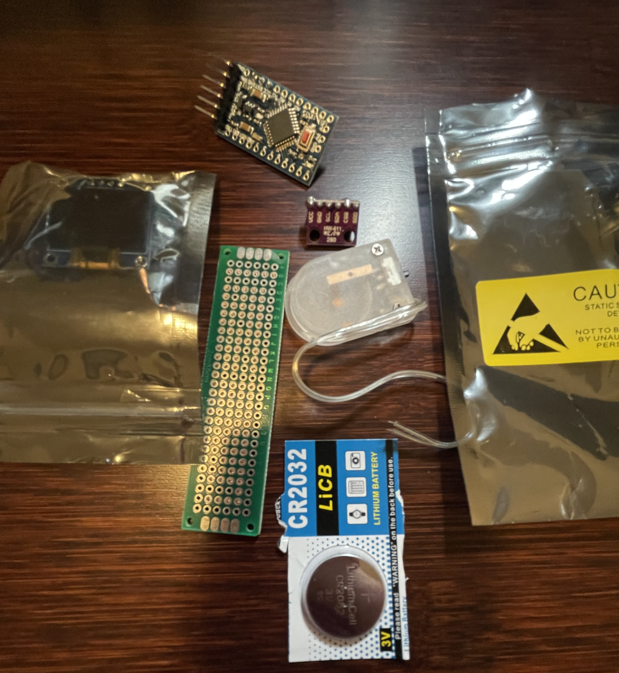
Inventory of components
Each of your bags contain one of the following
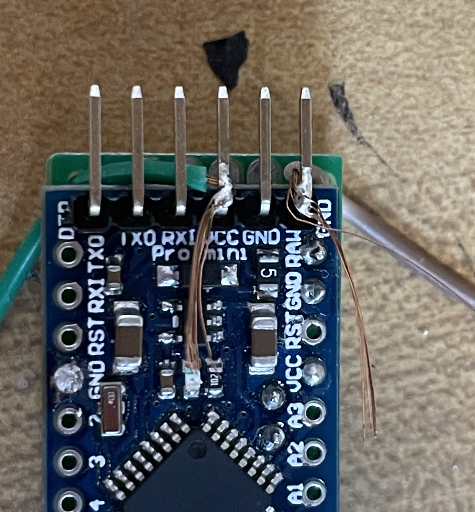
- Pre-configured Arduino Pro Mini 3.3v development board
- BMP2080 Temperature and Pressure sensor
- 128x64 LCD display (.96")
- 2cm x 8cm board with pre-laid circuitry
- Coin cell battery holder
- CR2032 3v Battery
What You'll Need
- A soldering iron
- some solder
Getting Started
- Get your bearings
First lay your components out make sure everything is there!
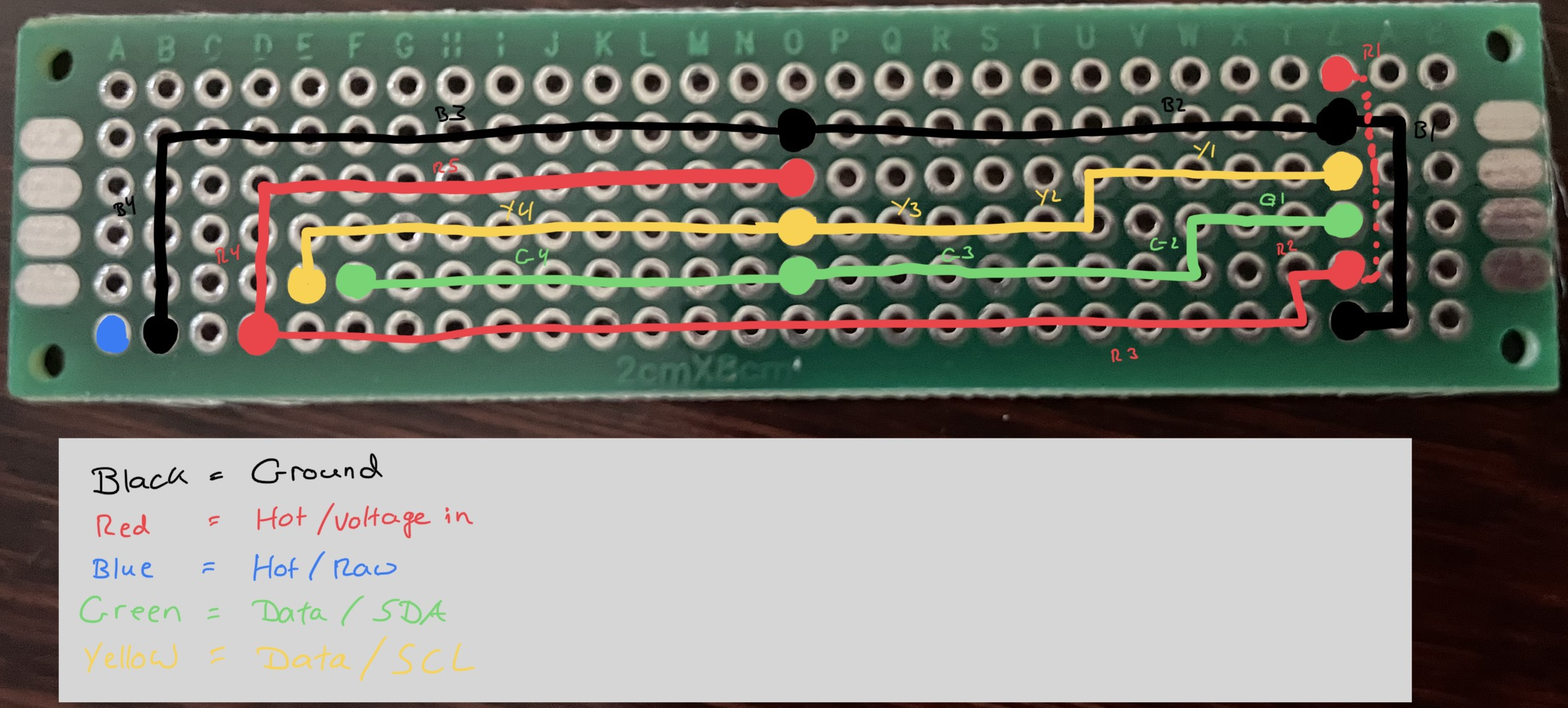
Review the below diagram to get a feel for where each component will end up.
The picture below is the bottom view of the board. A is the top, Z is the bottom.
2. Connect the Pressure Sensor
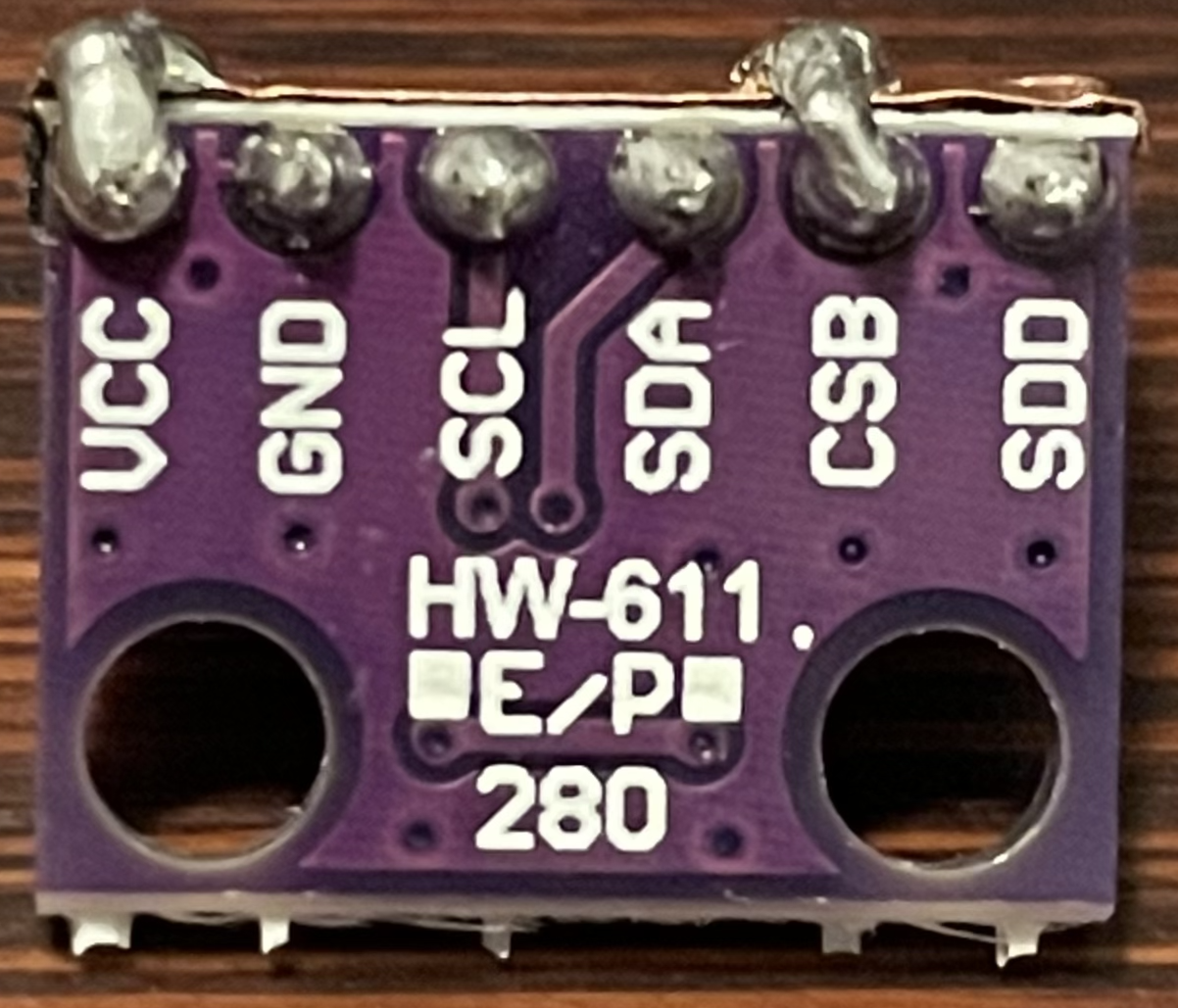
Find the BMP280 pressure sensor and orient it with the VCC pin so it will be in C1 if viewed from the top, or in Z1 if viewed from the bottom. Review Figure 2 above and make sure you know before the solder goes down that your sensor is aligned properly. Once you are ready, solder the six pins to the main board.
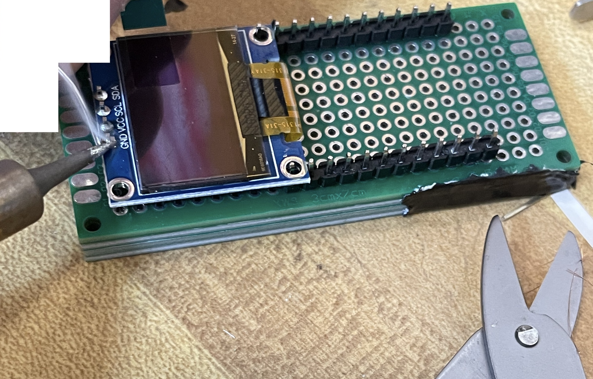
3. Connect the Display
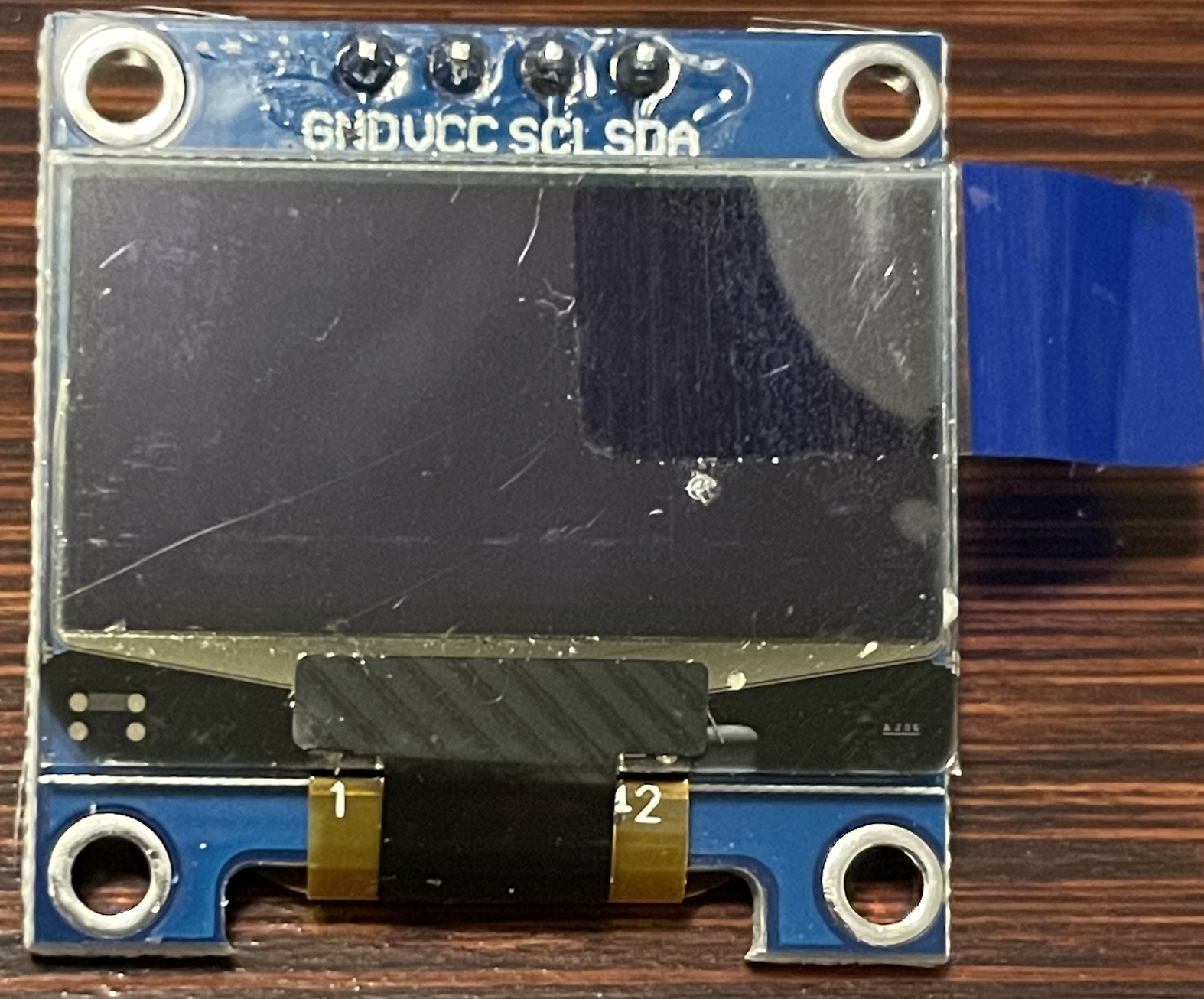
You can orient the display by noting which way you can read the pin labels, or by noting that the small cutout where the ribbon cable bends around behind the screen is the bottom. GRND should be in O2 when viewed from the back, and SDA in O4.
4. Connect the Arduino
You'll notice the arduino has a total of five pins soldered on the bottom, and an additional six in the front. Beginning underneath, the three in the lower left (B6-D6) are related to power. B6 is ground, D6 is voltage in or VCC. C6 is included for convenience, a single group of three pins was easier than two separate single pins. The remaining two pins, E5 and F5 are data pins for receiving info from the display and the sensor. The six pins at the top will be where we connect batteries and was also how I configured the Arduino.
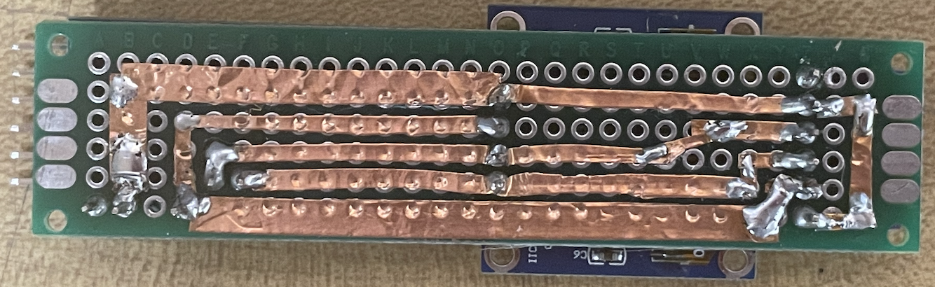
5. Solder Tape to Pins and solder the Tape
The conductive tape we used to lay the circuitry for the board has conductive glue too! technically, probably could have gotten away with not soldering all the joints like above, however, because we want these altimeters to be able to withstand whatever forces they deal with in a rocket, model airplane, drone, etc., we want this to be sturdy.
Look at figure 5 and see how each pin is soldered to the adjascent tape, and how the places where two pieces of tape connect, we solder that too. It doesn't take much solder, but adds a lot of strength.
6. Attach Battery Pack
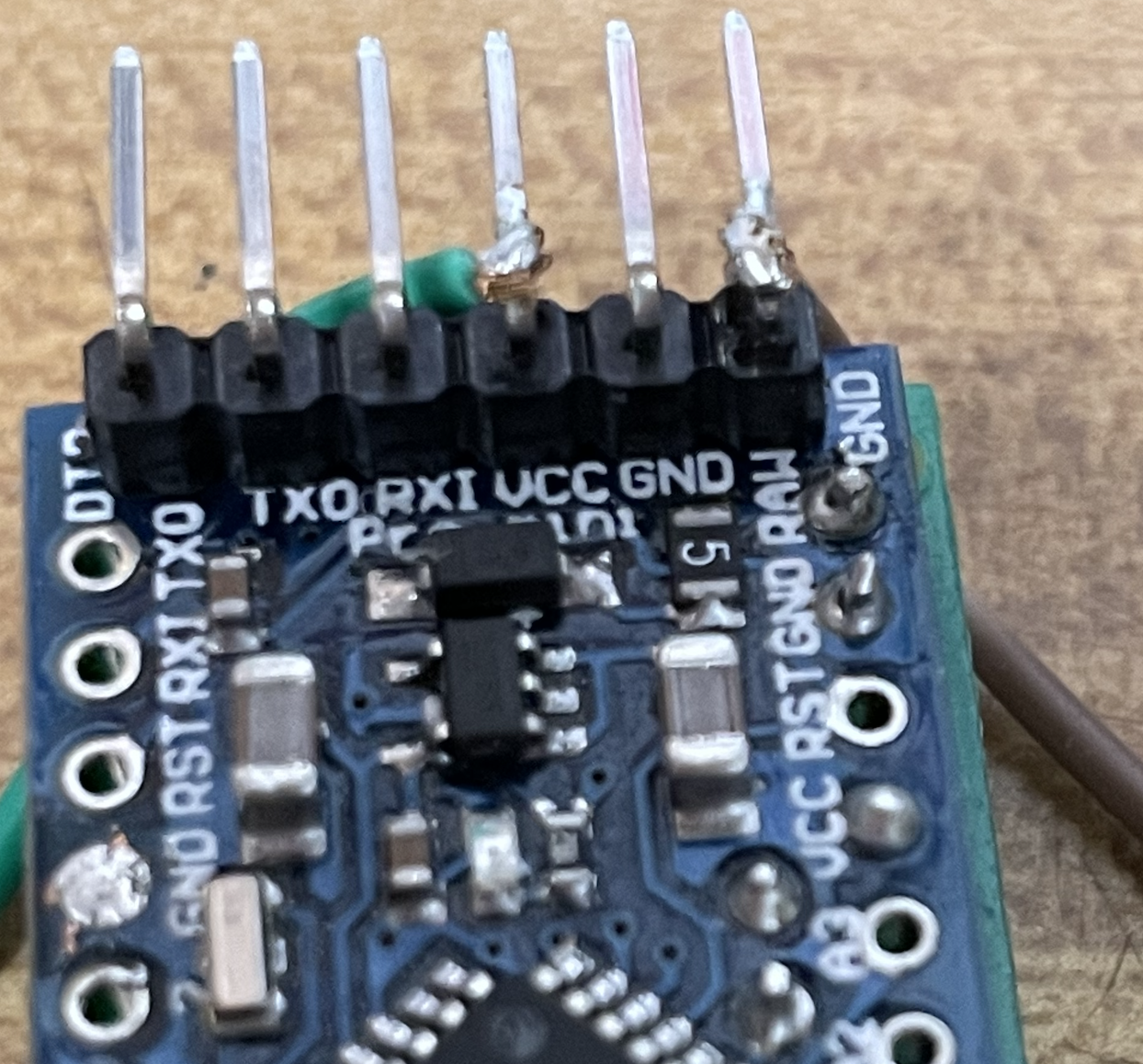
The arduino is preflashed so for simplicity we are going to connect the battery pack to the VCC and GND pins on the top of the device.
The wire with many difficult-to-see white blocks printed on the cable is positive (+). Run the positive lead through the small hole in the upper left side of the board and solder it near the bottom of the header pin labeled VCC. Then run the other the lead (has no markings) and is negative (-) through the small hole in the board on the upper right corner and attach it similarly to the GND pin. Cut the excess wires. Biggest thing to worry about here is just be careful not to accidentally bridge or connect two pins together. Could lead to electricity going places your new altimeter will not respond well to.
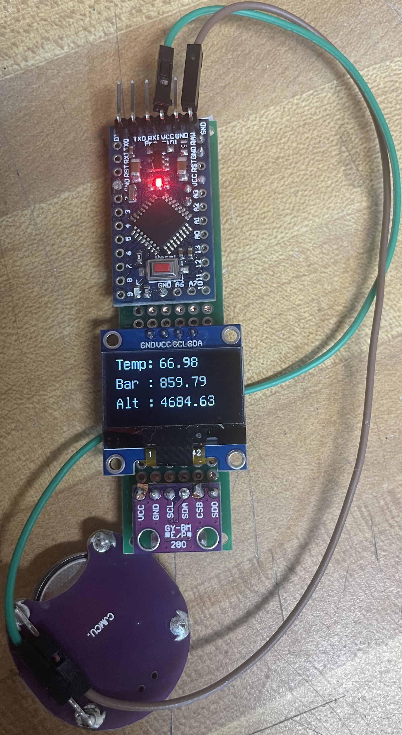
Note in the examples below I'm using a green wire for positive (+) and a brown wire for negative (-). Yours will look slightly different, but the principles are the same.
When ready to insert the battery, it should be oriented so that the positive terminal (top) facing the top of the battery case. Flip the switch on the battery pack to power it on!
Additional/Bonus Items
Soldering Tips
When soldering, do your best to heat the pad and press the solder to the hot iron and the heated target at about 45º-90º angle.
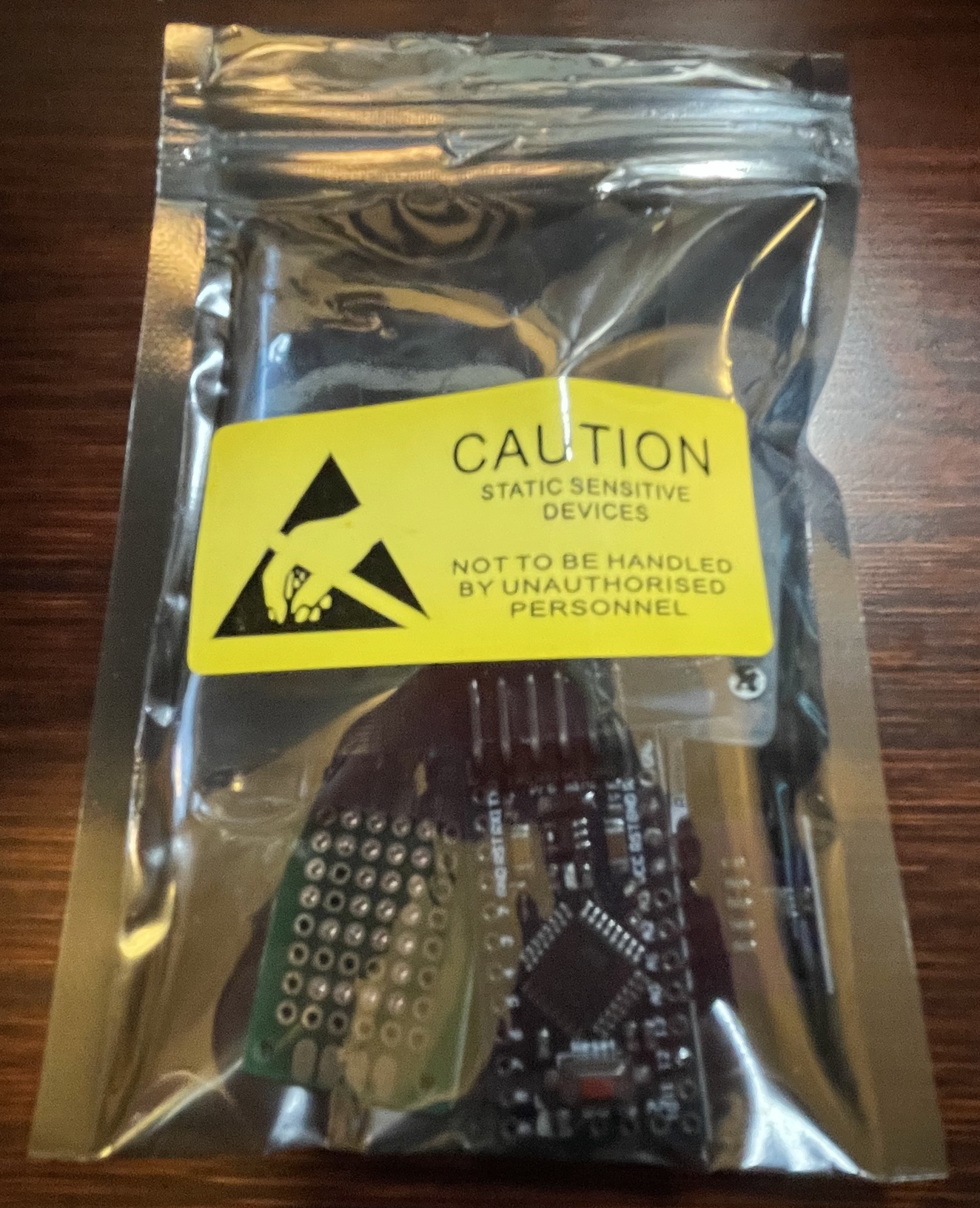
What do each of the components in the kit look like?